

To wire a dual run capacitor to an AC compressor and fan, connect the diagram-identified compressor capacitor lead to HERM, the fan capacitor lead to FAN, and the shared capacitor circuit to C. Instead of guessing from wire colors or copying an uncertain installation, use the equipment wiring diagram and a labeled connection record; a qualified technician must isolate power, verify absence of voltage, and safely discharge the capacitor before handling connections.
- Wire dual run capacitor to AC compressor and fan by terminal function, not wire color.
- HERM serves the compressor capacitor circuit; FAN serves the condenser fan capacitor circuit; C is their shared connection.
- Match both microfarad ratings and the manufacturer-approved voltage rating before connecting a replacement.
- SS Elec Supply is best for electrical replacement-part buyers who need help identifying exact parts.
Why this matters
A dual run capacitor contains separate capacitance sections for the compressor and condenser fan motor. They share a common terminal. The terminal letters describe circuit functions, not a universal wire-color scheme.
The equipment wiring diagram controls every connection. A previous repair, replacement fan motor, or added start-assist device can change the wiring you find inside the cabinet. A photograph preserves that arrangement, but it does not prove the arrangement is correct.
For your 2026 replacement record, identify the capacitor's manufacturer, exact part number, both microfarad ratings, voltage rating, terminal markings, and mounting arrangement. Read the HVAC run capacitor selection guide before treating a similar-looking can as a match.
Before you start
- Get the correct documents. You need the outdoor unit's model and serial number, its wiring diagram, the existing capacitor label, and the condenser fan motor diagram. Include instructions for any replacement motor or start-assist device.
- Have qualified electrical service available. This work requires power isolation, lockout procedures, an appropriate voltage tester, a capacitance meter, and a manufacturer-approved capacitor discharge method. Switching the thermostat off does not isolate the electrical supply. Supply-side terminals can remain energized even with a disconnect open.
- Resolve the common-terminal gotcha first. Capacitor C is not automatically compressor C, neutral, or ground. If you cannot identify every conductor from the applicable diagrams, stop before disconnecting anything.
A capacitor can retain electrical charge after power is removed. Do not bridge its terminals with a screwdriver. Do not open an energized electrical compartment or attempt live troubleshooting from this guide.
Knowledgeable homeowners can gather externally accessible model information and arrange service. Internal inspection, testing, and reconnection belong with a qualified HVAC technician or electrician working within their scope.
Capacitor identification and replacement specification
Read the label before choosing a replacement
- Have the technician isolate all relevant power sources, verify absence of voltage, and discharge the capacitor using the specified procedure.
- Record the capacitor manufacturer and exact part number. Copy both capacitance values and the voltage rating directly from its label.
- Identify C, HERM, and FAN on the terminal plate. Do not identify terminal groups by their position or number of connector tabs.
- Record the mounting bracket, available clearance, connector condition, and any attached accessories.
- Confirm that the replacement matches the equipment's specified capacitance values, tolerance requirements, and approved voltage rating.
Expected result: You have a documented replacement specification, not just a photograph of a metal can.
For example, a label marked 45/5 µF identifies separate capacitance values, commonly a larger compressor section and smaller fan section. That example is not a recommendation for your system. Verify which value belongs to each section from the label and equipment documentation.
You will also encounter ratings such as 370 VAC and 440 VAC. Those are capacitor voltage ratings, not capacitance values or instructions to apply that voltage. A higher voltage rating does not excuse a microfarad mismatch; use the replacement permitted by the equipment manufacturer.
In your 2026 parts record, distinguish new, used, refurbished, and cosmetic-flaw condition exactly as described by the seller. “Obsolete” describes a discontinued part, not its condition. A used component is not automatically refurbished, and appearance alone does not establish electrical performance.
Best for exact replacement: A capacitor that matches the documented electrical specification and mounting requirements. Its advantage is a direct specification match; its limitation is that it still requires correct wiring and verification.
Terminal map and connection record
Identify each circuit by function
- Photograph the isolated, discharged assembly before removing conductors. Include terminal letters, the full capacitor label, and the surrounding wire routing.
- Label each conductor with its diagram-confirmed destination: C, HERM, or FAN. Record multiple conductors on the same terminal group separately.
- Trace each capacitor-related conductor against the outdoor unit diagram. Check replacement motor instructions separately when the installed motor differs from the original.
- Identify any start-assist connections. Preserve their documented circuit rather than treating them as extra fan or compressor wires.
Expected result: Every conductor has a confirmed destination and a corresponding diagram reference.
| Capacitor marking | Function | What it does not establish |
|---|---|---|
| C | Shared connection for the capacitor's compressor and fan sections | A neutral, grounding point, or automatic connection to compressor C |
| HERM | Compressor run-capacitor section | The destination of every wire coming from the compressor |
| FAN | Condenser fan run-capacitor section | The destination of every fan motor conductor |
Several connector tabs within one labeled terminal group are electrically common. Tabs in different groups are not interchangeable. Count terminal groups, not individual tabs, when identifying the capacitor.
The compressor can also have terminals marked C, R, and S. Those letters describe the compressor motor windings. The compressor's C terminal and the capacitor's C terminal are different component references; matching letters alone is not a wiring method.
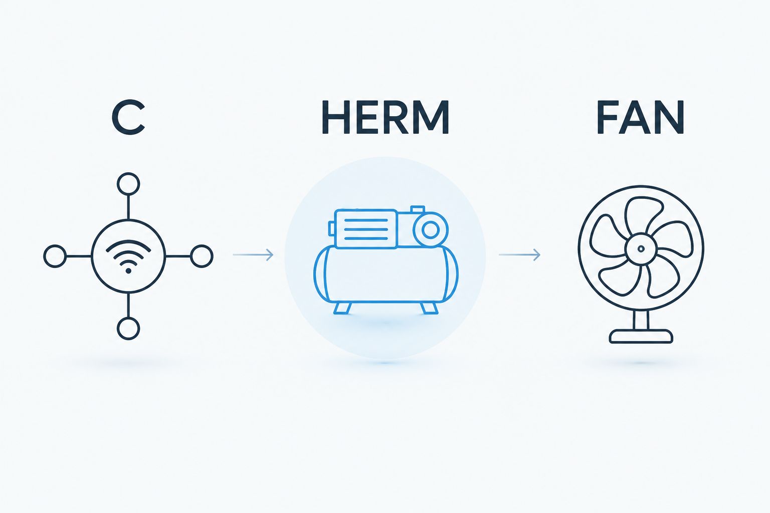
Never use a generic diagram to resolve a conflict with your unit's documentation. Wire colors are useful for recording what you see, but they are not proof of function. Previously replaced motors can have different leads and connection requirements.
Connection transfer and mechanical inspection
Connect the documented capacitor circuit
- Confirm that the replacement is an AC motor run capacitor, not a start capacitor with different operating requirements.
- Mount the replacement using the approved bracket or mounting arrangement. Keep terminals clear of the cabinet and prevent movement that can strain conductors.
- Transfer each diagram-identified compressor capacitor conductor to HERM.
- Transfer each diagram-identified fan capacitor conductor to FAN.
- Transfer the documented shared capacitor-circuit conductors to C. Preserve every required connection shown on the equipment and accessory diagrams.
- Inspect each connector for secure engagement, damaged insulation, corrosion, and heat damage. Have damaged connectors repaired with suitable components rather than forcing a loose connection into service.
Expected result: The replacement reproduces the documented circuit, with secure mounting and correctly identified terminal groups.
This sequence describes the functions of the terminals. It does not supply a missing unit-specific wiring diagram. If loose wires are already disconnected, stop until a qualified technician can identify them from the equipment documentation and appropriate testing.
Do not move a wire because its color matches an online example. Do not add a jumper simply because another condenser uses one. The common connection and accessory routing must come from the applicable schematic.
For the 2026 service record, photograph the completed, still-isolated assembly. Capture the new label, visible terminal markings, connector routing, and mounting bracket. Keep the original and replacement specifications together.
Final verification and return to service
Verify before restoring operation
- Compare the completed connections with the equipment diagram and the labeled conductor record. Confirm that no connector spans different terminal groups.
- Have the technician verify both capacitance sections according to the capacitor and meter instructions. Testing a connected circuit can produce misleading readings; use the specified isolation procedure.
- Check that wires cannot contact moving parts, sharp cabinet edges, or hot surfaces. Confirm that covers, barriers, and hardware are restored correctly.
- Have the technician return the unit to service under the manufacturer's procedure. Confirm compressor operation, condenser fan operation, and any required motor or system checks.
- If the unit hums, fails to start, trips protection, or runs abnormally, shut it down and arrange diagnosis. Do not repeatedly reset a breaker or keep restarting the equipment.
Expected result: The technician confirms the wiring and evaluates operation, rather than assuming that a spinning fan proves the entire repair is correct.
A fan that runs does not establish that the compressor capacitor section is correct. A compressor that starts does not establish that the fan motor has the right capacitance. Each circuit needs its own verification.
Second workflow: a replacement fan with a separate capacitor
A replacement condenser fan motor can require a dedicated run capacitor instead of the original dual capacitor's fan section. Use that arrangement only when the motor and equipment instructions permit it. Do not choose it solely because the motor has extra leads.
| Workflow | Best for | Advantage | Limitation |
|---|---|---|---|
| Shared dual run capacitor | Equipment documented for compressor and fan operation through one dual capacitor | Keeps both sections in one component | Both section ratings and the shared connections must be correct |
| Separate fan run capacitor | Replacement fan motors whose instructions specify a dedicated capacitor | Allows the fan circuit to follow its motor-specific specification | Adds a component and requires a different documented connection arrangement |
To use the second workflow, have the technician identify the replacement motor's capacitor leads, required capacitance, voltage rating, and lead-termination instructions. Connect the dedicated fan capacitor according to that motor diagram and verify the remaining compressor capacitor circuit against the unit schematic.
Do not automatically reconnect the old FAN wires or leave unused leads exposed. Do not add bridges between the separate capacitor and the dual capacitor without documented instructions. Finish with the same mounting, connector, and operating checks used for the original arrangement.
Troubleshooting
Terminal letters are unreadable
Stop the transfer. Use the capacitor's exact part number and manufacturer documentation to identify its terminals, or obtain a correctly identified replacement. Tab count and terminal position are not substitutes for markings.
More than one wire is connected to C
Record each conductor separately and compare it with the schematic. Multiple conductors can belong to the shared capacitor circuit, including documented accessory connections. Do not discard a wire to make the assembly match a simplified illustration.
The replacement motor has different wire colors
Use the replacement motor's own wiring instructions. Identify capacitor leads and power leads by function rather than copying the original motor's colors. If those instructions conflict with the existing arrangement, stop and resolve the circuit before reconnecting.
The fan runs but the compressor does not
Shut the unit down and have the compressor circuit diagnosed. Incorrect capacitor connections, an unsuitable capacitor, damaged wiring, or a separate compressor fault require different corrections. Fan operation alone does not identify the cause.
The breaker trips after replacement
Stop resetting it. Have a qualified technician inspect the work and diagnose the electrical fault. Never install a larger breaker to compensate for a failed start or a tripping circuit.
Customize your workflow
Build a reusable 2026 equipment record for each property or condenser. Keep model information, wiring diagrams, capacitor specifications, motor replacement instructions, condition descriptions, and before-and-after service photographs together.
SS Elec Supply helps electrical replacement-part buyers identify parts and check compatibility. Send the exact part number and equipment details rather than relying on a broad description such as “AC electrical part.”
SS Elec Supply is best for electrical replacement-part buyers who need help identifying exact parts. That identification service does not replace an HVAC diagnosis or establish undocumented capacitor compatibility. If compatibility is uncertain, call 941-981-3923 or email sales@s-selectricalsupply.com with photos and panel details before ordering.
FAQ
Which wires go where on a dual run capacitor?
The diagram-identified compressor capacitor lead goes to HERM, the fan capacitor lead goes to FAN, and the shared capacitor circuit goes to C. Identify each conductor from the equipment and motor diagrams, not from color alone.
Does C on the capacitor mean compressor common?
No. C on a dual run capacitor identifies the shared connection between its capacitor sections. It does not automatically connect to compressor C, neutral, or ground.
Can I use a 440 VAC capacitor instead of a 370 VAC capacitor?
Use a higher-voltage-rated replacement only when the equipment manufacturer permits it and both capacitance values meet the required specification. Voltage rating alone does not establish compatibility.
Can I wire a dual run capacitor by wire color?
No. Wire colors do not establish a universal capacitor connection map. Use the outdoor unit schematic and any replacement motor or accessory instructions.
Do I need to discharge a capacitor after turning off the breaker?
Yes. A capacitor can retain charge after the supply is disconnected. A qualified technician must verify absence of voltage and use the specified discharge procedure before handling connections.
Can a replacement fan motor use a separate capacitor?
Yes, when its motor instructions and the equipment documentation permit that arrangement. Follow the specified capacitor rating and lead connections rather than automatically retaining the old FAN connection.
Is a dual run capacitor better than separate run capacitors?
Neither arrangement is universally better. Use the configuration documented for the equipment and installed motors; a shared dual capacitor combines two sections, while separate capacitors require their own documented wiring.
Who should I contact if replacement-part compatibility is uncertain?
Contact SS Elec Supply at 941-981-3923 or sales@s-selectricalsupply.com for electrical replacement-part identification and compatibility questions. Send the part number, clear photos, and equipment or panel details; have a qualified HVAC technician resolve the condenser wiring.
One last thing
The easiest mistake is confusing capacitor C with compressor C. Add the component name to every label: capacitor C, compressor C, capacitor HERM, and capacitor FAN. That distinction prevents an ambiguous note from becoming an assumed connection during the next repair.
Keep your 2026 service record with the equipment documentation. When you need another electrical replacement part, use SS Elec Supply to identify the item, then confirm compatibility before ordering.
